Services
Product Q&A
Common problems with Inclinometer / Tilt Sensor

1. No data output

Possible causes: The device is not powered on; the wiring is loose or has poor contact; the wiring is incorrect; the communication parameters are mismatched; the host computer software is used improperly; the customer's hardware is incompatible; the device is faulty.  

General processing steps:  

① Confirm the device model and verify the power supply and wiring contact status. It is recommended that the customer test via USB on a computer to verify that the operating environment is normal.

② Confirm the default communication protocol parameters: For Serial port communication protocol, the protocol is typically 9600 N 8 1, with a default address of 0; the Modbus (MB) protocol is typically 9600 E 8 1. Note that the customer may have modified the parameters; it is recommended to remind the customer to recall or consult relevant colleagues.

③ Verify the wiring definitions. For RS-232 or TTL interfaces, ensure the communication lines are cross-connected and that the signal ground and power ground share a common ground (usually the signal ground and power ground are on the same end, which can be led out from the negative terminal). For RS-485 interfaces, D+ corresponds to A, and D- corresponds to B.

④ Confirm that the software interface parameter settings are consistent with step 2; for more detailed operation, refer to the software operation manual. Pay special attention to the fact that incorrect Modbus protocol checksum settings are a common problem.


2. Angle value abnormal  

① Check if the installation orientation is correct. You can try restoring the absolute zero point and then testing.

② If using our universal host computer, confirm that the range and resolution settings in the real-time data interface are correct. The range can be referenced to the device model; the resolution is typically 0.01 (applicable to STS, LTS, and NTS series). For high-precision products, please refer to the datasheet.

③ If the customer's self-developed software experiences parsing errors, we recommend using our standard host computer for comparison testing.

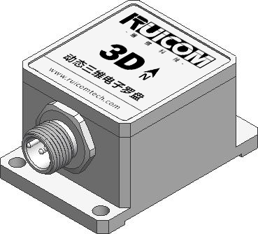
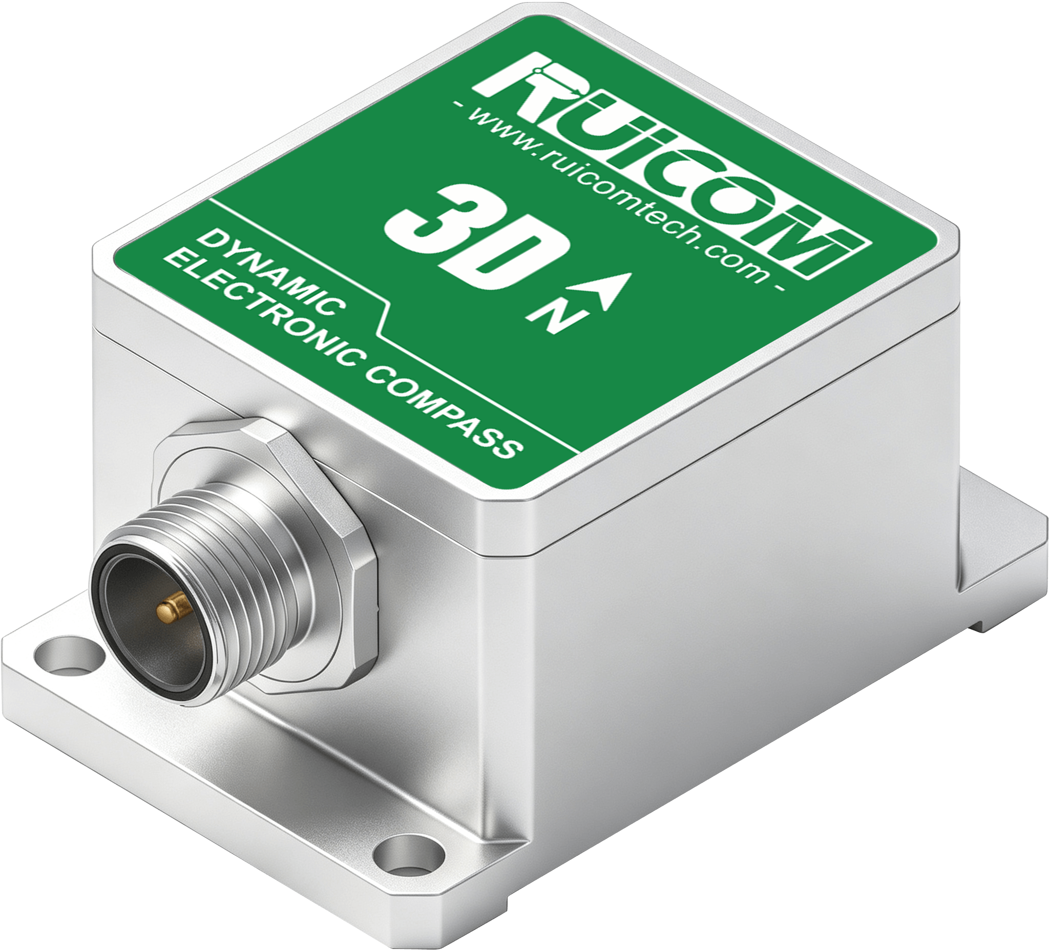
Common problems with 3D electronic compasses


1. No data output

Possible causes: The device is not powered on; the wiring is loose or has poor contact; the wiring is incorrect; the communication parameters are mismatched; the host computer software is used improperly; the customer's hardware is incompatible; the device is faulty.

General processing steps

① Confirm the device model and verify the power supply and wiring contact status. It is recommended that the customer test via USB on a computer to verify that the operating environment is normal.

② Confirm the default communication protocol parameters: For Serial port communication protocol, the protocol is typically 9600 N 8 1, with a default address of 0; the Modbus (MB) protocol is typically 9600 E 8 1. Note that the customer may have modified the parameters; it is recommended to remind the customer to recall or consult relevant colleagues.

③ Verify the wiring definitions. For RS-232 or TTL interfaces, ensure the communication lines are cross-connected and that the signal ground and power ground share a common ground (usually the signal ground and power ground are on the same end, which can be led out from the negative terminal). For RS-485 interfaces, D+ corresponds to A, and D- corresponds to B.

④ Confirm that the software interface parameter settings are consistent with step 2; for more detailed operation, refer to the software operation manual. Pay special attention to the fact that incorrect Modbus protocol checksum settings are a common problem.


2. Azimuth accuracy issue

Possible causes: Environmental interference; lack of calibration; unstable power supply; improper calibration procedure.

Recommendations:

① It is recommended that customers choose an open space for testing, away from magnetic equipment; avoid using magnetic comparison tools (such as mobile phone electronic compasses); multiple compasses should not be tested together to prevent mutual interference.

② After changing the testing environment, it is recommended to recalibrate. Calibration requirements can be found in the relevant operation video. Basic calibration conditions include: rotating one full revolution for at least 20 seconds, and ensuring no power interruption during the process.

③ Unstable power supply voltage may cause azimuth fluctuations; ensure a stable power supply.

④ Abnormal calibration processes may cause data deviations, which can be corrected by re-performing the calibration.


Common Gyroscope Issues


1. No data output

Possible causes: The device is not powered on; the wiring is loose or has poor contact; the wiring is incorrect; the communication parameters are mismatched; the host computer software is used improperly; the customer's hardware is incompatible; the device is faulty.

General processing steps

① Confirm the device model and verify the power supply and wiring contact status. It is recommended that the customer test via USB on a computer to verify that the operating environment is normal.

② Confirm the default communication protocol parameters: For Serial port communication protocol, the protocol is typically 9600 N 8 1, with a default address of 0; the Modbus (MB) protocol is typically 9600 E 8 1. Note that the customer may have modified the parameters; it is recommended to remind the customer to recall or consult relevant colleagues.

③ Verify the wiring definitions. For RS-232 or TTL interfaces, ensure the communication lines are cross-connected and that the signal ground and power ground share a common ground (usually the signal ground and power ground are on the same end, which can be led out from the negative terminal). For RS-485 interfaces, D+ corresponds to A, and D- corresponds to B.

④ Confirm that the software interface parameter settings are consistent with step 2; for more detailed operation, refer to the software operation manual. Pay special attention to the fact that incorrect Modbus protocol checksum settings are a common problem.


2. Angle Drift

① Failure to maintain a stationary state during startup may lead to abnormal initial data.

② The device itself has time-drift characteristics and is affected by external factors such as vibration. Drift is a normal phenomenon and needs to be evaluated in conjunction with the specific usage environment.

③ The presence of vibration sources in the usage environment may exacerbate the drift.


Common Issues with IMU Inertial Navigation Products

1. No output from the device.

Possible causes: The device is not powered on; the wiring is loose or has poor contact; the wiring is incorrect; the communication parameters are mismatched; the host computer software is used improperly; the customer's hardware is incompatible; the device is faulty.  

General processing steps:  

① Confirm the device model and verify the power supply and wiring contact status. It is recommended that the customer test via USB on a computer to verify that the operating environment is normal.

② Confirm the default communication protocol parameters: For Serial port communication protocol, the protocol is typically 9600 N 8 1, with a default address of 0; the Modbus (MB) protocol is typically 9600 E 8 1. Note that the customer may have modified the parameters; it is recommended to remind the customer to recall or consult relevant colleagues.

③ Verify the wiring definitions. For RS-232 or TTL interfaces, ensure the communication lines are cross-connected and that the signal ground and power ground share a common ground (usually the signal ground and power ground are on the same end, which can be led out from the negative terminal). For RS-485 interfaces, D+ corresponds to A, and D- corresponds to B.

④ Confirm that the software interface parameter settings are consistent with step 2; for more detailed operation, refer to the software operation manual. Pay special attention to the fact that incorrect Modbus protocol checksum settings are a common problem.

2. Data values and related settings. 

Please refer to the product specification sheet. We recommend using the standard host computer provided by our company for operation.

Common problems with electronic levels and digital display devices

1. Unable to power on

Check if the device has power and if the buttons are responsive.


2. Abnormal angle values

① Angle value stagnation: Try pressing the reset button or restarting. If ineffective, the device may be faulty.

② Accuracy deviation: Some digital display devices require setting latitude parameters. Please confirm that the latitude setting is correct. If the user manually zeroes the absolute zero point, ensure the zeroing operation is performed on a high-precision platform; otherwise, deviations may occur.

③ Incorrect data values: Confirm whether the user pressed the zeroing button at a large angle.

④ Data fluctuations: Confirm whether the device is tested in a stationary state. If stationary, try adjusting the internal output frequency; lowering the frequency is recommended to reduce fluctuations.
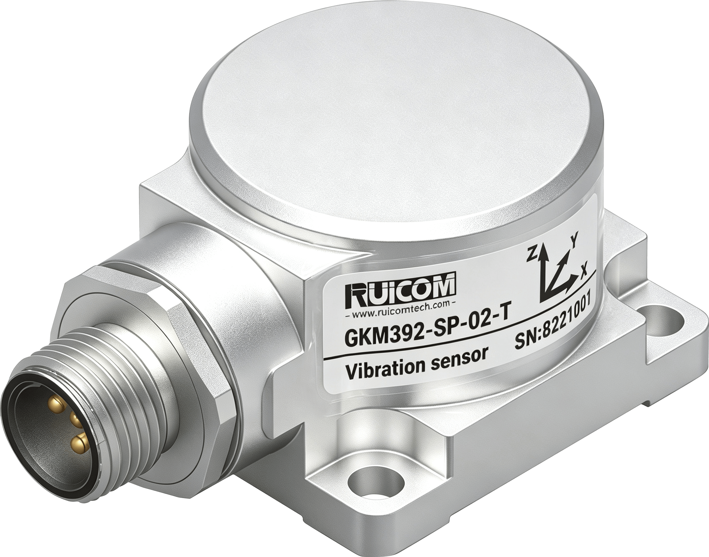
Common problems in the use of vibration sensor products

1. No data output

Possible causes: The device is not powered on; the wiring is loose or has poor contact; the wiring is incorrect; the communication parameters are mismatched; the host computer software is used improperly; the customer's hardware is incompatible; the device is faulty.  

General processing steps:  

① Confirm the device model and verify the power supply and wiring contact status. It is recommended that the customer test via USB on a computer to verify that the operating environment is normal.

② Confirm the default communication protocol parameters: For Serial port communication protocol, the protocol is typically 9600 N 8 1, with a default address of 0; the Modbus (MB) protocol is typically 9600 E 8 1. Note that the customer may have modified the parameters; it is recommended to remind the customer to recall or consult relevant colleagues.

③ Verify the wiring definitions. For RS-232 or TTL interfaces, ensure the communication lines are cross-connected and that the signal ground and power ground share a common ground (usually the signal ground and power ground are on the same end, which can be led out from the negative terminal). For RS-485 interfaces, D+ corresponds to A, and D- corresponds to B.

④ Confirm that the software interface parameter settings are consistent with step 2; for more detailed operation, refer to the software operation manual. Pay special attention to the fact that incorrect Modbus protocol checksum settings are a common problem.

2. Abnormal Acceleration Value:

① Confirm that the software used is compatible with the model.

② In a stationary state, a Z-axis display of 1G is normal, representing gravitational acceleration.

③ Check the wiring and module status; the RS-232 interface communication cable length should not exceed 10 meters, and if the RS-485 cable is too long, ensure a common ground.

Common Usage Issues of Wireless IoT Inclinometers

1. Unable to connect to the platform

① Confirm that a SIM card is inserted and that it is an IoT card; China Telecom cards require authorization, but China Mobile cards are recommended; verify that the card is activated and bound.

② Confirm that the device is powered on normally and that the antenna connection is reliable (this also applies to devices with built-in antennas).

③ Verify that the platform parameter configuration is correct and that the platform allows external network access; confirm that the platform protocol is compatible with the product (our products mainly support TCP and MQTT protocols), and that the device has been added to the platform.

④ Verify that the product parameter settings are correct (including protocol, topic, IP address, data format, etc.).


Notes:

- Model number must be confirmed before processing any product.

- If customers request code or algorithm information, the standard response is that it is not convenient to provide it.

- For neutral model products, please contact our sales staff to verify the information before processing.

- For products involving the Modbus protocol, customers frequently inquire about PLC connection-related issues. The default parameters are as follows:

✮ Account number is 01 by default

✮ First register address is 0002H (corresponding to 40003)

✮ Function code is 03H

✮ Data type is typically a 32-bit unsigned integer, little-endian (little-first).
1